

分類: 未分類
Fluoroscopy
Reference materials for learning fluoroscopy
1. Guidelines on fluoroscopy (Room 6, DR) v5 – Department of Radiology, TMH.

2. A guide to radiological procedures, by Stephen Chapman.
General information
1. Common drugs to be used in fluoroscopy
2. Rule of LMP check in different fluoroscopic examination
Fluoroscopic examinations
a) Gastrointestinal systems
1. Barium swalow
2. Barium meal
3. Barium enema
4. Water soluble contrast follow-through for small bowel obstruction
5. T-tube cholangiogram
6. Sialogram
7. Loopgram/pouchgram
b) Respiratory system
1. Diaphragmatic screening
c) Genitourinary system
1. Micturiting cystourethrogram (MCUG) for pediatric patients
2. Urethrogram
3. Hysterosalpinogram (HSG)
Fluoroscopic sialogram – Overview
Introduction
– Fluoroscopic / conventional sialography ( aka. radiosialography ) is a radiographic examination of the salivary glands and ducts by cannulation and injection of contrast medium into the duct
( N.B. Sialogram can be done only for parotid and submandibular gland, but not sublingual gland as the ducts for sublingual gland is almost impossible to cannulate )
– Fluoroscopic / conventional sialography is now largely been replaced by CT and MR sialography of salivary glands, but still fluoroscopic sialography is more superior in terms of :
1. Higher spatial resolution : Can accurately delineate second to third order branches ( requires shooting film rather than screening )
2. Therapeutic values : May dilate strictures or retrograde displacement of sialolith to relieve acute obstruction
Indications
– Common indications include :
1. Suspected sialolithiasis or other obstruction ( e.g. strictures )
2. Suspected sialadenitis : identify ductal strictures
3. Suspected sialectasis in chronic inflammatory disorders and autoimmune diseases
Contraindications
– Contraindications include :
1. Contrast media allergy
2. Periods of acute inflammation or infections of salivary ducts
3. Clinical examination / radiographs reveal calculus close to ductal opening
Complications
– Possible complications of fluoroscopic sialography :
1. Pain or rupture of ducts : Reduced by not to over-inject contrast into ductal system ( up to 2 mL )
2. Infection : Reduced by massaging of glands and giving lemon juice to express the contrast material
3. Damage to duct orifice : Reduced by using lemon juice for saliva expression to aid cannulation
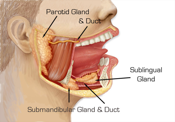
Anatomy of 3 pairs of major salivary glands
– Parotid gland :
1. Anatomy of gland : Largest major salivary gland that lies just below the zygomatic arch in front and below the external ear
2. Anatomy of duct : Parotid duct ( aka. Stenson’s duct ) is 5cm long, running over the masseter and opens into oral vestibule opposite to 2nd upper molar
– Submandibular gland :
1. Anatomy of gland : Second largest salivary gland that extends from inferior 1st molar to angle of mandible
2. Anatomy of duct : Submandibular duct ( aka. Whartsons duct ) is 5cm long, running forward, medially, upward on side of frenulum
– Sublingual gland :
1. Anatomy of gland : Smallest pair of major salivary gland, located in the floor of mouth on the surface of mylohyoid muscle
2. Anatomy of duct : Numerous, small sublingual ducts ( aka. Rivinus ducts ) open into floor of mouth, sometimes, ducts may join to form a single duct which empties into the submandibular duct
Procedures
– Patient’s preparation : Remove any radio-opaque foreign objects ( e.g. false teeth )
– Preliminary radiographs : Detect for any radio-opaque stones, same for both paroid and submandibular sialography
1. Anteroposterior : Head rotated 5% away from the side of investigation
2. Lateral oblique : Angle the tube 20% cephalad

– Preparation of equipment :
1. Contrast media : Iodine-based contrast media, water soluble contrast media is used as it can fill finer ductal structures and cause less allergic reactions compared to oil-based contrast media
2. Syringes : There would be 5ml and 1ml synringes, prime the syringes with contrast medium, higher pressure of injection can be produced by syringes of smaller volume
3. Extension tube : To be connected to the cannula and the syringe for injection to be done from a distance from the patient, while the operating radiologist can stay behind the lead shield while screening
4. Lemon juice : To aid identifying the papilla of salivary duct ( see below ) and help excretion of contrast after the study
– Identification and cannulation of papilla of salivary duct :
1. Patient is lied supine and is asked to open the mouth to identify possible sites of papilla of duct based on anatomical landmark :
a) Parotid gland : Beside upper 2nd molar
b) Submandibular gland : On each side of frenulum
2. Expression of saliva to make the papilla opening conspicuous for cannulation :
a) Dip the area dry with gauze
b) Give few drops of lemon juice to the oral cavity ( stay away from the papilla ), there will be saliva secretion ( i.e. liquid secretions +/- tiny bubbles over the papilla )

3. Graded probes may be used to dilate the duct before cannulation
4. Size of cannulation catheter use :
a) Parotid’s duct : 21 gauge
b) Submandibular duct : 24-27 gauge
5. After successful cannulation, the system has to be fixed in position, best by 3 point fixation techniques :
a) Patient close the mouth and gently bite down to hold the catheter
b) Tape to stick the extension tube on patient’s face
c) Tape to stick the extension tube on fluoroscopy bed / lead screen, etc
– Contrast injection and film taking :
1. Up to 2 mL of contrast medium is injected.
Injection is terminated immediately if any pain is experienced by the patient.
2. Repeat films with same views as in preliminary films
– After the examination :
1. Remove the cannula catheter by the radiologists
2. Ask patient to rinse the mouth, give some lemon juice and educate the patient to self massage the salivary gland to help express the retained contrast
Reference :
1. Credit to Dr. P Lee and P Cheung. Fluoroscopy session, 27/8/2019 am & 29/10/2019 am.
2. Sialography. Radiopedia.
3. A guide to radiological procedures. Sialography.
4. Sialograms and sialography. University of LOWA Health Care.
Middle-aged ex-smoker presented with shortness of breath
Patient’s history :
56 years old male who was an ex-smoker with 5 pack-years. No family history of cancer. He was initially presented with shortness of breath and palpitations 3 months ago, chest X-ray was done. There was no hemoptysis nor significant constitutional symptoms. His vital signs are relatively stable.
Study the following radiograph :
– Initial chest radiograph 3 months ago :

– Follow-up chest X-ray 1 month later :

– Latest chest X-ray 1 month ago :

– Latest PET-CT done in private :

Discussion :
– This patient develops shortness of breath with CXR showing apparently clear lung fields, we need to consider paying more attention to look for any :
1. Small pneumothorax : Only a faint line of visceral pleura
2. Upper lobe venous diversion : Only feature of early sign of congestive heart failure
3. Small volume loss : Checking for deviation of mediastinal structures, hila and hemidiaphragm
– For the initial chest X-ray, when we examine the hilar shadow, the right hilum is abnormal because :
1. Contour : A bulging contour over the right suprahilar region seen
2. Radio-opacity : The right suprahilar mass has a relatively higher radio-opacity compared to the bilateral hilum
The right suprahilar mass does not have a very well distinct lateral border, so it is likely a lung mass rather than an extrapulmonary in origin
– The position of the right hilum is still considered normal as its hilar point is still located lower than the left side. But in the next FU chest X-ray, there is right upper lobe collapse secondary to the obstruction of right upper lobe bronchus by the mass, giving rise to a classical sign known as Golden S sign or reverse S sign of Golden :
1. Superolateral part : Concave and is more well-distinct, signify elevated right horizontal fissure
2. Inferomedial part : Convex and is less distinct, signify the bulging right suprahilar mass.
The mass shows interval increase in size with increasing right lung volume loss as shown in the latest chest X-ray 1 month ago.
– Atelectasis / lung collapse is one of the earliest manifestations of bronchogenic carcinoma, Golden S sign is one of the special form of atelectasis that suggest high chance of underlying malignancy causing the collapse.
– The Golden S sign was first described by Ross Golden in 1925 in conjunction with bronchogenic carcinoma of lung, which is still remains the most common cause of this radiological sign. But this sign actually signifies only a centrally obstructing mass causing right upper loeb collapse, other less common differential diagnoses include :
1. Mediastinal lymphadenopathy or lymph node metastasis from other carcinoma
2. Primary mediastinal tumors.
– Golden S sign is not only a radiographic sign but can also be seen on axial CT scan. In contrast to radiographic Golden S sign, CT scan can demonstrate Golden S sign for collapse of any lobes due to centrally located mass lesion and is more sensitive than plain film :
1. Lobar collapse : Concave border formed by the fissure that arcs toward the hilum.
2. Centrally obstructing mass : Disrupt the usual concave course of fissure by giving a convex bulge

– The best next step of further investigation would be pathological diagnosis via bronchoscopy as the lesion is near central part of airway. In case it is bronchogenic carcinoma, both non-small cell and small cell lung cancers are possible. But small cell lung cancers are much worse in prognosis as most patients on diagnosis demonstrate distant metastasis. Another investigation for any oncological diseases would be PET-CT to look for the extent for possible staging to guide management.
Progress of this patient :
– The PET-CT confirmed a large hypermetabolic mass over RUL occluding the right upper lobe bronchus with multiple mediastinal lymph node metastasis. One thing to be particularly important to look for for patient having a right suprahilar mass is any SVC obstruction, which is not present in this patient.
– Bronchoscopy and endobronchial ultrasound was attempted, but it failed because of the compressed right upper bronchus does not allow the instrument to pass through. Therefore, a precarinal LN FNAC was done and revealed small cell carcinoma and was referred to oncology for further care.
Reference :
1. Credit to Dr. N Ip. Film review session – 29/8/2019 pm.
2. Golden S sign (lung lobe collapse). Radiopedia.
3. S sign of Golden. Learning Radiology.
4. Golden “S" sign. Moti Lal Bunkar, et al.
5. The Golden S sign. Radiology. Punita Gupta, et al.
6. Computed tomography appearance of Golden “S" sign. James W. Reinig, et al.
CT anatomy of pericardium
Background
– Pericardium consists of outer fibrous pericardium and the inner serous pericardium which appears in CT as a thin line < 2 mm, as this corresponds to :
1. Pericardial tissue : Fibrous and serous pericardium
2. Pericardial fluid within serous pericardium : 20-25mL physiologically

– The pericardium can only be visualised when it is sandwiched between pericardial fat pad, which can be subdivided into :
1. Epicardial fat : Fat deposited between the heart and pericardium
2. Paracardial / mediastinal fat : Fat deposited outside pericardium

– The pericardial cavity is the fluid containing space within the serous pericardium, pericardial recesses / sinuses are fluid pockets formed around great vessels due to reflection of the serous pericardium appearing as near-water density in CT scan ( depending on the amount of fluid filled )
– Difference of CT imaging of pericardium between past and present :
1. In the past :
a) Thicker sections : Depict occasionally some large pericardial sinuses only
( e.g. superior aortic recess, left pulmonic recess, etc )
b) Longer scan time : More motion artefacts
2. Nowadays :
a) Thinner sections : Even smaller pericardial sinuses can be seen
b) Shorter scan time and cardiac gating technique : Less motion artefact
Anatomy of pericardial sinuses / recesses
– Pericardial sinuses or recesses can be divided into :
1. Transverse sinus ( blue ) : Lies behind ascending aorta ( aortic recess ) and pulmonary artery ( pulmonic recess ), which are subdivided into :
a) Aortic recess : Superior ( anterior and posterior portion ) and inferior aortic recess
b) Pulmonic recess : Left and right pulmonic recess
2. Oblique sinus ( green ) : Lies behind left atrium
3. Postcaval recess ( orange ) : Lies behind superior vena cava
4. Pulmonary venous recess ( red ) : Left and right pulmonary venous recesses

Pericardial sinuses in real CT images
– Transverse sinus :
1. Anterior portion of superior aortic recess : Triangular shaped space located posterior to ascending aorta above pulmonary trunk
2. Posterior portion of superior aortic recess : Hemispheric space located posterior to ascending aorta above pulmonary trunk
3. Inferior aortic recess : Linear space located posterior to root of aorta below pulmonary trunk
4. Left pulmonic recess : Crescentic space located between pulmonary trunk and left pulmonary vein
5. Right pulmonic recess : Irregular shaped space located between pulmonary trunk and right pulmonary vein, usually irregular in shape
– Oblique sinus : Spindle shaped space located posterior to left atrium
– Postcaval recess : Oval shaped space located posterior to the superior vena cava
( N.B. Owing to frequent streak artefact at SVC due to presence of contrast, postcaval recess is the least commonly seen )
– Pulmonary venous recess :
1. Left pulmonary venous recess : Hemispheric space located posterior to left pulmonary vein
2. Right pulmonary venous recess : Hemispheric space located posterior to right pulmonary vein


– The superior aortic recess usually has upper border at the sternal angle ( i.e. carina ) but high riding superior aortic recess can travel up to tracheal levels filling the pretracheal space ( mimicking upper paratracheal lymph nodes )

Pericardial recess mimic mediastinal lesions or pathology
– Knowledge of some pericardial recesses / sinuses is important because they can be visualised in CT nowadays which may simulate pathology of hilum and mediastinum, particularly when there is pericardial effusion :
1. Anterior portion of superior aortic recess may mimic type A aortic dissection
2. Various pericardial recesses may mimic enlarged mediastinal lymph nodes and cystic mediastinal mass lesions :
a) Thymic cysts
b) Bronchogenic cysts
c) Pericardial cysts
– Normal mediastinal lymph nodes may appear adjacent to pericardial recesses :
1. Paraaortic lymph nodes : Lie anterior and lateral to the ascending aorta or aortic arch, which is near anterior portion of superior aortic recess
2. Left lower paratracheal lymph nodes : Lie at the left lateral surface of trachea between upper margin of aortic arch to that of left main pulmonary artery, which is near posterior portion of superior aortic recess


3. Subaortic lymph nodes : Lie in the AP window lateral to the ligamentum venosum, near the left pulmonic recess
4. Left hilar lymph nodes : Lie Lie adjacent to the left main stem bronchus, near the right pulmonic recess
5. Paraesophageal lymph nodes : Lie adjacent to the esophagus, near the oblique sinus
6. Right hilar lymph nodes : Lie adjacent to the right main stem bronchus, near the postcaval recess
7. Pulmonary ligament lymph nodes : Lie within pulmonary ligament, near the pulmonary venous recess
( N.B. Although lymph nodes can be differentiated from pericardial sinuses by having a denser attenuation and usually oval in shape, yet only knowledge of anatomy of pericardial recesses can help differentiate between oval shaped recesses and LN )
Reference :
1. Comparing thin-section and thick-section CT of pericardial sinuses and recesses. Furmlko Kodama, et al.
2. Mediastinum – Lymph node map. Radiology Assistant.
3. The superior sinus of the pericardium: CT appearance. Dixie J. Aronberg, M.D.
4. The anatomy of the pericardial space: A study in cadavers and patient. Yeon Hyeon Choe, et al.
5. The “high-riding" superior pericardial recess: CT findings. Yo Won Choi, et al.
6. Pericardial sinuses and recesses: Findings at electrocardiographically triggered electron-beam CT. Gottfried Schaffler, et al.
Middle-aged woman with Down’s syndrome presented with shortness of breath
Patient’s history :
56 years old hostel resident has known Down’s syndrome with large perimembranous ventricular septal defect, no surgical operation was done so far. She is on long term O2 of about 1-2L/min and was admitted for shortness of breath and cyanosis.
Study the following radiographs :
– This was the chest radiograph about 10 years ago :

– This is the most recent chest radiograph :

Discussion :
– This case demonstrates the importance of progress chest radiographs still serve a good tool for evaluation in congenital heart disease, although echocardiography remains the gold standard.
– Pulmonary vascular pattern is divided into :
1. Normal lung vascularity
2. Increased lung vascularity ( aka. Pulmonary plethora )
3. Decreased lung vascularity ( aka. Pulmonary oligemia )
– For normal vascularity, an upright chest X-ray should demonstrate the following features :
1. Gradual tapering towards the periphery of lungs
2. Vascular markings are more prominent in lower than upper lung zones.
a) The apical region should be devoid of sizable vascular markings
b) Normal descending pulmonary artery has similar diameter as the trachea
( Serve as a reference only as coronal tracheal width may be affected e.g. in Saber-sheath trachea in COPD and some tracheal pathology )

– The first radiograph demonstrates pulmonary plethora ( i.e. increased pulmonary vascularity ) which means uniform enlargement of the whole pulmonary arterial system :
1. Pulmonary trunk : Convex bulge of the pulmonary arterial segment of left heart border
2. Left and right main pulmonary arteries : Straightening or bulging contour of bilateral hilar shadow
3. Peripheral pulmonary arteries :
a) Descending branch : Diameter greater than that of trachea
b) Ascending branch : Visible in apical area
– Pulmonary plethora should be distincted from ordinary congestive heart failure features :
1. Upper lobe venous diversion : The lung markings at the lower zone is not particularly distended, while for pulmonary plethora, the whole pulmonary arterial system is distended
2. Perihilar alveolar edema ( bat wing sign ) : The prominent hilar shadow has a well defined border, in contrast to hazzy border of the perihilar alveolar edema in congestive heart failure.
( N.B. If the left-to-right shunt of congenital heart defect is complicated by congestive heart failure, both features will be mixed together )

– Pulmonary plethora can be either :
1. Pulmonary cause : Cor pulmonale e.g. secondary to chronic lung diseases, thus we may look for :
a) Retrictive lung diseases : Reticular pattern, volume loss
b) Obstructive lung diseases : Hyperinflated lungs with flattening of hemidiaphragm, emphysematous changes and Saber-sheath trachea in GOLD stage III-IV COPD
2. Cardiac cause : Acyanotic congenital heart disease causing a left-to-right shunt, for example :
a) Atrial septal defect : Due to defect in atrial septum ( e.g. Patent foramen ovale, sinus venosus defect, etc )
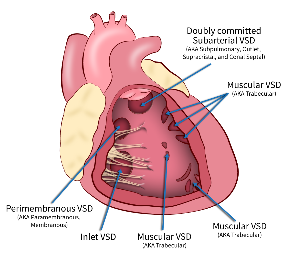
b) Ventricular septal defect : Due to defect in in various parts of the ventricular septum ( e.g. Subaortic, perimembranous, inlet, muscular, etc )
c) Atrioventricular septal defect : From left heart to right heart due to inadequate fusion of mid portion of atrial septum and muscular portion of ventricular septum
d) Patent ductus arteriosus : Blood from aorta travels to pulmonary arteries through the unobliterated ductus arteriosus
( N.B. Pulmonary plethora can also be seen in hyperdynamic circulatory state e.g. pregnancy, thyrotoxicosis, severe anaemia, etc )
– Noted that pulmonary plethora in plain radiograph occurs when pulmonary blood flow (Qp) is at least double that of systemic blood flow (Qs). CXR can be used to estimate the extent of Qs by degree of pulmonary vascularity, but not an accurate quantitative tool as the degree of pulmonary vascularity depends on other factors ( e.g. heart rate, contractility )
– Both the first and second radiograph shows features of pulmonary plethora :
1. Straightening / bulging contour of pulmonary trunk segment of left heart border, suggestive of distended pulmonary trunk
2. Bulging contour of bilateral hilar shadows, suggestive of distended main pulmonary artery
3. Sizable arteries are seen at apical regions, suggestive of distended ascending branches of pulmonary artery
4. Diameter of descending branch of pulmonary arteries are larger than the width of trachea, suggestive of distended descending branches of pulmonary artery
– Both radiographs do not demonstrate features of congestive heart failure which is a possible complication of congenital heart disease :
1. The contour of prominent hilum is distinct ( i.e. not perihilar consolidation )
2. Absence of Kerley B’s line and pleural effusion
– The second radiograph, compared to first radiograph, shows apparent normalization of pulmonary plethora, suggestive of less pulmonary blood flow. Together with development of cyanosis, these imply the development of Eisenmenger syndrome with equalization of pressure between bilateral ventricles causing a bidirectional shunting. This can be seen as a late complication of long-term left-to-right shunt as there is a gradual increase in pulmonary vessel’s resistance upon persistent pulmonary hypertension, result in right ventricualr hypertrophy.
– Down syndrome is commonly associated with AVSD / VSD, which is confirmed by transesophageal echocardiogram in this patient. But surgical repair is no longer useful when Eisenmenger syndrome has occured as the pressure between both ventricles have already been equalised.
Progress of this patient :
– She was managed with IV lasix and symptoms improve, this implies although no features of congestive heart failure in CXR, there can still be component of congestive heart failure clinically.
Reference :
1. Credit to Dr. Kwok and Dr. Siu. Film review session. 8/10/2019 pm and 9/10/2019
2. Pulmonary plethora. Radiopedia.
3. The chest x-ray in congenital heart disease 1. Total anomalous pulmonary venous drainage and coarctation of the aorta.
4. The chest x-ray in congenital heart disease 2. Images Paediatr Cardiol.
5. Pulmonary vascularity. Radiology Key.
6. Saber sheath trachea. Radiopedia.
7. Saber-sheath trachea as a marker of severe airflow obstruction in chronic obstructive pulmonary disease
CT Brain
Resources that I used to learn readign CT Brain :
1. Reading books, I would recommend :
– Fundamentals of body CT, by W. Richard Webb, et al.

2. Use web-based reference resources, I would recommend :
– Radiology assistant, by Robin Smithuis MD
![]()
– CTisus, by Professor Elliot K. Fishman :

3. Searching for literatures for specific issues about reading the CT
4. CT review sessions with seniors at TMH. In real life, history from epr and comparison with previous film are essential. It is always more equivocal for real life cases as they are not particularly selected for demonstration unlike those in books. The judgement to call or not for any lesion and give corresponding suggestion is an art that can be learnt from seniors.
Real case discussion :
These are the cases that I meet during my training in the Department of Radiology, Tuen Mun Hospital, cases with learning points are included below :
Middle aged man with progressively enlarging hilar mass
Patient’s history :
A 60 years old male with known history of hypertension and hyperlipidemia. He attended AED for chest wall pain. Otherwise no shortness of breath, no hemoptysis. There is no history of chest wall injury.
Study the following radiograph :

Progress chest X-ray 3 months :

Progress contrast CT thorax at the level of hilum 1 week later :


Discussion :
– The initial chest X-ray shows a bulging opacity over right hilar with increased radio-opacity compared to the left side, it can be lymphadenopathy or lung mass, that is why progress CXR and CT thorax are suggested.
( N.B. You may refer to this case for hilum assessment )
– Progress CXR shows interval increase in right diameter of the right hilar mass, thus underlying malignancy is very likely given that it has a fast growth rate even without a CT scan available yet at that time point. More careful review of the CXR shows also 2 new features :
1. Elevated right hemidiaphragm
2. New expansile lytic lesion over 5th rib
– Concerning the elevated right hemidiaphragm, you may refer this case for the approach to determine the possible underlying cause. This patient has no obvious features point to lung atelectasis and fibrosis nor any significant volume loss with equal rib spaces on both sides. There is no previous lung surgery done. The contour of the diaphragm is maintained, thus subpulmonic effusion, eventration of diaphragm are less likely. Bowel is seen over right upper quadrant of abdomen but not dilated to the extent that can cause elevation of the right hemidiaphragm. Since there is a progressively enlarging right hilar mass, the most possible cause of the new elevated hemidiaphragm is due to external compression of the right phrenic nerve.
– The phrenic nerve travels vertically along the lateral wall of mediastinum :
1. Above thoracic inlet : In between subclavian artery and vein
2. Great vessels level : Run beside SVC and arch of aorta
3. Hilar level : Run anterior to the hilum
4. Cardiac level : Run on both sides of the pericardium
Therefore, although we can only visualise the increase in transverse diameter of the hilar mass in frontal CXR, we may deduce there might have increased in AP diameter also causing compression of the ipsilateral phrenic nerve, causing new elevated right hemidiaphragm. This is confirmed in the contrast CT thorax 1 week later.

– Another way a hilar mass causing elevated hemidiaphragm is by obstruction of bronchus causing collapse, but no features of lung collapse and we would expect a much more obvious lung volume loss in contrast to that for phrenic nerve compression.
– There is a new expansile lytic lesion over the right rib, noted that it is an aggressive bony lesion instead of callous formation of rib fracture because :
1. The border is ill-defined suggestive of aggressive periosteal reaction while callous formation of fractured bone is non-aggressive periosteal reaction which has clear margin. See this case for assessment of periosteal reaction.
2. Fast growth rate ( new lesion not seen in past CXR 3 months ago )
3. Further supported by absence of chest wall injury history.
Progress of this patient :
– PET/CT reveals hypermetabolic R hilar mass between RUL bronchus and RBI, highly supsicous of malignancy. There are also multiple pleural deporsits over R lung. There is bone metasis over R 5th rib, R acetabulum, T11/ T16 early bone metastasis.
– Attended private with brochoscopy and biopsy done, pathology comes back to be AdenoCa, ALK +ve.
– Patient is now under the care of oncology department and is put on Crizotinib.
Reference :
1. Credit to Dr. N Ip – Film review session 3/10/2019 pm.
2. Credit to Dr. Kwok – Film review session 30/9/2019 am.
3. Elevated hemidiaphragm. Radiopedia.
Old age home resident noted to have deformity of left elbow
Patient’s history :
85 years old female OAHR who was bedridden, non-communicable currently on tube-fed. She had history of schizophrenia. History given from OAH staff stated that they notised there was left elbow deformity and swelling. Physical examination revealed shortening and deformity of the left distal humerus. The radial and ulnar pulses are still palpable. No open wound noted.
Study the following radiograph :

Discussion :
– There is comminuted supracondylar fracture of the left distal humerus with dorsal angulation of the distal fragment, surrounding soft tissue swelling is also seen, but there is no joint effusion noted. It is always ideal to have both AP and lateral view because :
1. More easily pick up the fracture lines, which may appear in only one view sometimes
2. Determine the direction of angulation of bony fragment, which guides maneuver of reduction
3. Lateral view to look for any elevated anterior fat pad ( known as sail sign ) signifying joint effusion.

– Supracondylar fracture is commonly seen in young patient with high energy trauma, although some are multi-fragmentary and open in nature, but since the bones are normal thus usually amendable to secure fixation after reduction.
– For elderly patient, supracondylar fracture is most commonly due to slip and fall at the point of elbow, the olecranon is driven into the trochlea which splits the osteoporotic humeral condyles into displaced fragments. Since this patient is bedridden, the possibility of negligence or even abuse has to be considered.
– In contrast to young patients, degree of osteoporosis and the age are key consideration to decide between surgical and conservative management. For conservative management, poor elbow function and chronic pain are likely to occur.
Progress of the patient :
Close reduction under c-arm with long arm slab. Swelling is releived with upper limb elevation and ice therapy. Orthopedic team planned for conservative management and optimal pain control.
Reference :
1. Credit to Dr. N Ip. Film review session – 3/10/2019 am.
2. Supracondylar fractures of the humerus. Orthipedic proceedings.
3. Sail sign (elbow). Radiopedia.
Incidental finding of elevated hemidiaphragm of male with known hepatitis B
Patient’s history :
76 years old obese male non-smoker and non-drinker. He has a known history of poorly controlled DM, hypertension and hyperlipidemia. He was found to have hepatitis B positive and USG revealed fatty liver and cirrhotic changes. No hepatomegaly seen. No previous lung operation done. He is otherwise asymptomatic.
Study the following radiograph :

( Note : No previous chest X-ray for comparison. )
Discussion :
– This patient has acceptable inspiratory effort over the left lung by counting the number of ribs and the rib space on both sizes are comparable, suggesting that the elevated left hemidiaphragm is not due to suboptimal inspiration but other causes.
– Classifications of hemidiaphragm elevation allows us to look for other clues :
1. Above diaphragm :
a) Pathological : Decrease lung volume ( Atelectasis / collapse ) with features of other volume loss
b) Iatrogenic : Evidence of lobectomy
2. Diaphragm :
a) Phrenic nerve palsy : Mass lesion along ipsilateral border of mediastinum
b) Diaphragmatic eventration : Abnormal contour of hemidiaphragm
c) Contralateral stroke with middle cerebral artery distribution
3. Below diaphragm ( i.e. Abdomen ) :
a) Subpulmonic effusion : Distorted diaphragm contour
b) Subphrenic abscess
c) Organomegaly ( e.g. hepatomegaly, splenomegaly, liver metastasis, etc ) or distended stomach or colon
– Concerning this patient, there is no obvious lung collapse or linear opacities suggestive of atelectatic or fibrotic changes, nor any mediastinal mass seen. The contour of the dipahragm is still preserved, so subpulmonic effusion or diaphragmatic eventration is less likely. There is also no distended bowel noted at the abdominal region. Recent ultrasound abdomen revealed no hepatomegaly nor any subphrenic mass or abscess. Clinically he is asymptomatic without any neurological deficit.
– One possible cause can be congenital phrenic nerve palsy, in case there is past film for comparison showing new onset of elevated hemidiaphragm, diabetes associated with phrenic nerve palsy as this can be the presentation of mononeuritis due to diabetic microvascular complication.
– In fact most of the time no exact cause is known, but elevated hemidiaphragm is significant as it can be clue to liver and lung mass.
Reference :
1. Credit to Dr. Kwok. Flim review session – 2/10/2019 am.
2. Elevated hemidiaphragm. Radiopedia.
3. Phrenic Neuropathy in Association with Diabetes. Diabetic medicine.
